Gree Sapphire Install + Home Assistant Integration

A couple of weekends ago, I installed our home's first mini-split.
Our home has two existing forms of conditioning - an oil fired boiler in the basement feeds hydronic baseboard radiators, and a hearthstone wood stove in the living room. The wood stove is great and practically free to run (100+ acres of woods means I'll only ever run out of desire to cut it down), but heats in waves and struggles to reach the edges of the house. I sleep like a rock and never feed it in the middle of the night, so by morning the house is pretty chilly in the winter. It also can't be run safely while we're gone, leaving the oil boiler to pick up the slack. Heating oil is expensive! Neither of these options provide any relief in the only-getting-hotter summers. I have long wanted to add cooling + heating flexibility with ductless minisplits.
I adhere to a strict no contractor rule, so I was on the hunt for a DIY friendly option. Near as I can tell, all minisplits are made by a small number of companies, mainly Gree and Midea. There are a bunch of rebranded units, like Sennville and Mr. Cool, but I found a company out of Kentucky that appears to warranty DIY installs. More importantly, via reddit, I was able to map one of their models directly to a Gree unit. The Blue Ridge S5 series is just a Gree Sapphire. These Gree units boast some of the highest SEER and HSPF on the market and have a local polling home assistant add-on, both huge wins in my book.
I started off with a 12000BTU unit for our bedroom. Here are the tools and materials I purchased for the install:
- Blue Ridge S5 12000BTU Single Zone Condensor+Indoor Head
- 50 foot lineset from Alpine
- Drain hose
- Nylog blue sealant
- Diversitech Wall Sleeve for lineset and cables
- Electrical Disconnect, whip, and indoor unit signal cable
- Condensor pad
- CPS Micron Vacuum Gauge
- Vevor 2 stage 7CFM Vacuum Pump
- Yellow jacket charge hose
- Yellow jacket ball valve
- Appion vacuum rated 5/16" valve core removal tool
- Appion vacuum rated 1/4" valve core removal tool (to isolate vacuum gauge, attaches to other valve core removal tool)
- Vevor lineset covers
- Hole saw kit
- Crows foot wrenches
- Scale for refrigerant
- 25lb R410A refrigerant
First, I mounted the indoor head unit. I lined up the bracket and hung drywall anchors to fix it to the wall. I referred to the sapphire users manual for minimum clearances to the ceiling/walls. I punched a hole with a hole saw and fed the diversitech wall sleeve through it, spray foaming around the outside to seal everything. I stuffed the inside of the sleeve around the lineset with duct seal - it's malleable and would allow me to pull the split out without ripping a bunch of spray foam apart.

Next was roughing in the lineset. I ran the lineset and multiconductor electrical cable down and under my sunroom, exiting under the deck where I planned to place the condensor. I bought a set of crows foot wrenches and planned to use them with a torque wrench to tighten the lineset lines to both the condensor and the lines from the indoor unit, but my biggest wrench was too small for the larger of the two lines. I used the crows foot to tighten the smaller line. For the bigger line, I took my half inch torque wrench and calibrated my forearm to the torque specified in the sapphire manual. I then tightened the lineset connections with two crescent wrenches. Before tightening either, I applied a small dab of nylog blue to the flare connections. At the wall sleeve, I stuffed in some duct seal to make everything air tight. Under the sunroom and deck, I suspended the lineset to the studs using plumbing hanging strap.
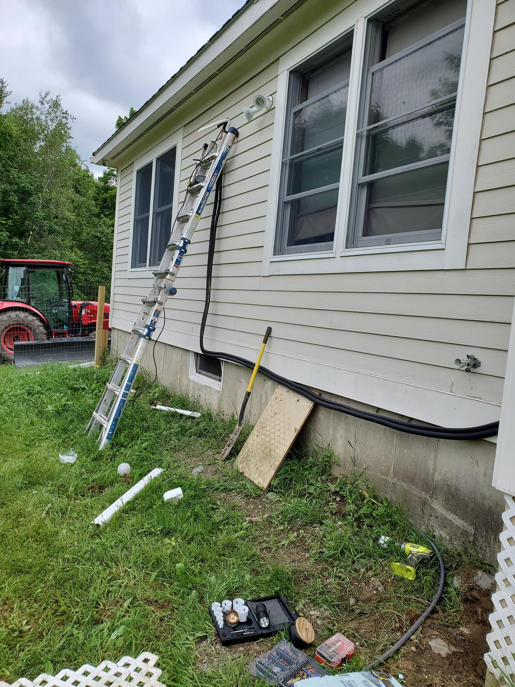
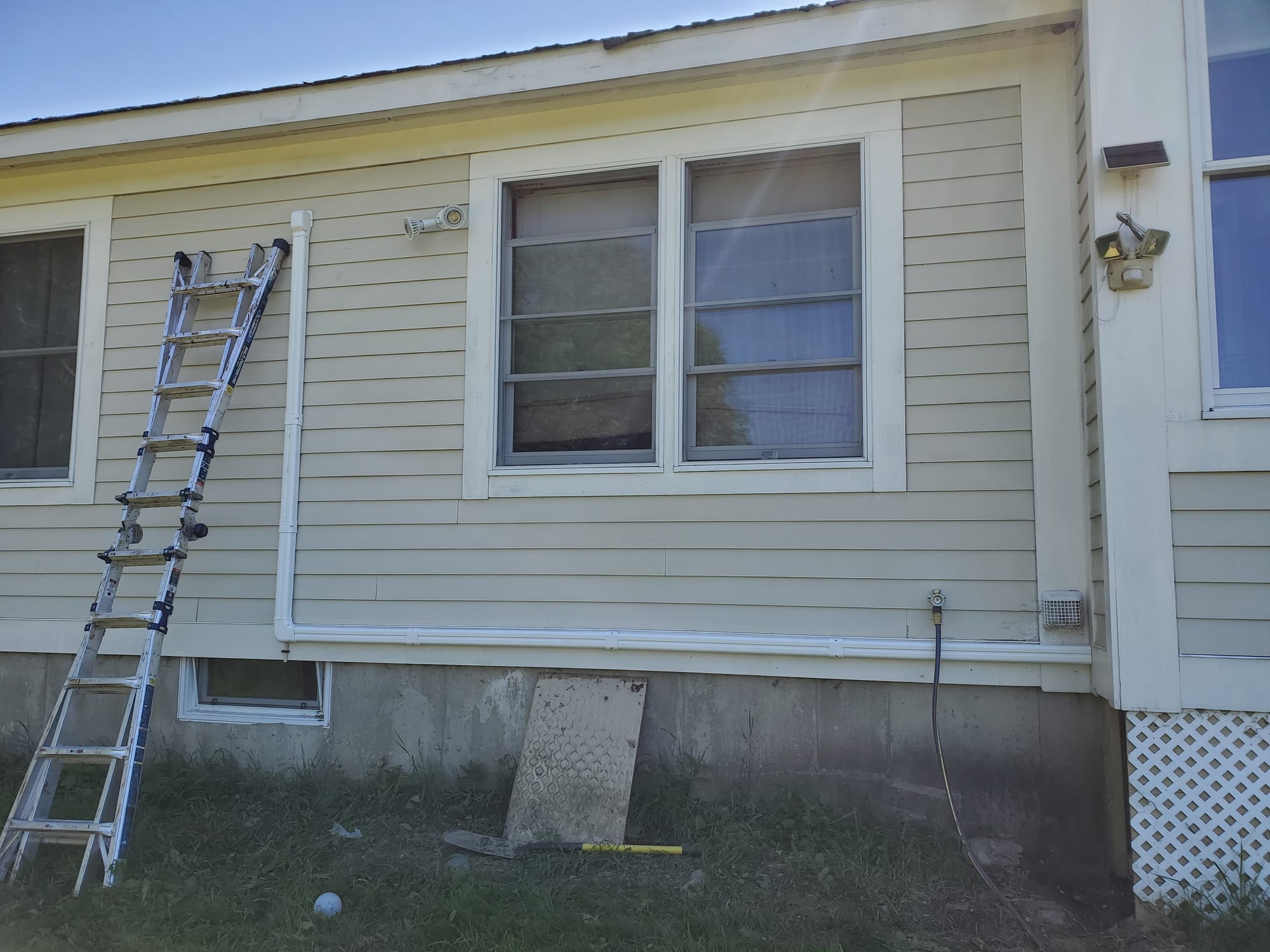
Next was lineset covers. I opted to buy 3" vevor lineset covers - these were great looking and about half the price of the diversitech offerings. I secured it to the siding with 1.5" screws and snapped the front pieces on. For the drain line, I drilled a small hole in the bottom of the first elbow at the end of the vertical run. I extended the flexible piping a few inches beyond the siding and secured it with a PEX clamp.
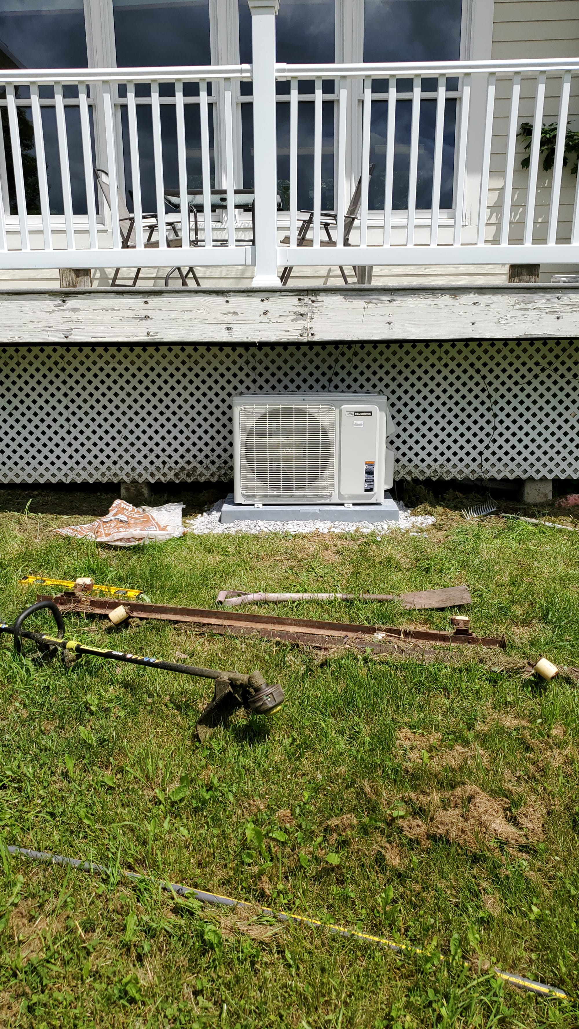
Next was placing the condensor. I flattened out and made a level gravel pad then placed the plastic condensor pad on top. If I could do it again, I'd raise the unit off the pad a few inches (I ended up having to cut a slot in it to fit the refrigerant valve + line on the service ports - I'll 3d print a little cap to fill in this area at some point), but I was cutting it close on vertical clearance. I chose under the deck because it was a nice covered area that should keep the unit out of the elements most of the year.
After the pad outdoor unit was set, I ran 12/2 underground feeder from a 20A breaker in my panel to the local disconnect, and a 10ga whip from the disconnect to the minisplit condensor. I made final connections at the condensor (lineset + electrical run from condensor to indoor unit) and prepared to pull a vacuum.
For final preparation, I closely followed this procedure by AC service tech. I pulled the shraeder valve from the service port, hooked up a micron vacuum gauge using a second valve core removal tool (to isolate the vacuum gauge later in the procedure), and hooked up my vacuum pump. I pulled a vacuum down to under 200 microns, let the lines equalize, and watched for vacuum decay. Decay was extremely slow and eventually settled out at around 330 microns. It held this level for over an hour. I pulled a deeper vacuum down to 140 microns and let it sit awhile longer. At this point, I was satisfied the system was evacuated and leak free.
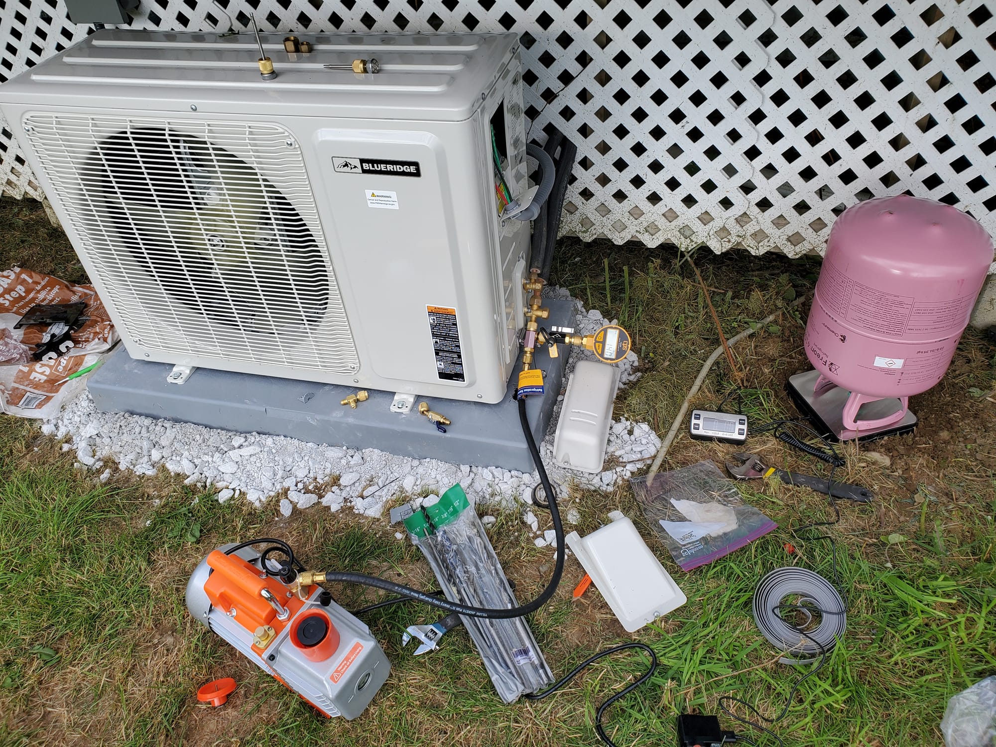
I had to run a 50 foot lineset and the Gree unti was only precharged for 25 feet, so rather than immediately opening the king valve and releasing all of the refridgerant in the compressor into the lineset, I added an additional 5oz of R410A to the system. I took the same hose I used to vacuum + a yellow jacket shutoff valve, purged everything with a bit of R410A just like in the video, and then charged an additional 5oz. Instead of a dedicated refrigerant scale to monitor the weight of the 25lb R410A cylinder, I used a harbor freight postal scale. This worked great. Finally, with the system charged and under pressure, I re-inserted the valve core with the valve core removal tool and opened the king valves. The physical install was complete!
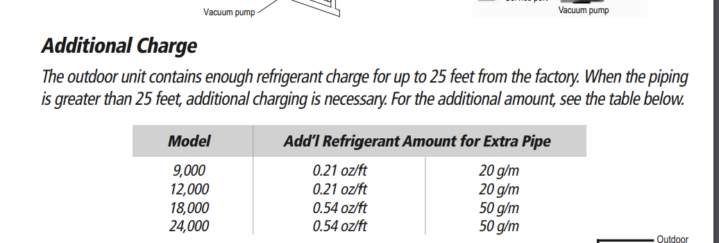
The one step I skipped was a pressure test with nitrogen - from what I gather, this is typically done before vacuuming to make sure all flare connections are solid. I didn't have an easy source of nitrogen cylinders. Using a micron vacuum gauge, rather than a manifold gauge set as is sometimes used by DIYers, I figured I'd be able to determine a leak by vacuum decay. After releasing the refrigerant, I took some soapy water and sprayed down each flare joint (inside unit going to lineset and lineset to condensor) - I saw no bubbles.
Now, for the fun stuff. I had a lot of trouble getting the Gree+ app to connect to my minisplit. When I went to add it automatically, it'd fail at 49% and throw a generic error. From what I found on reddit, this seems to be a common problem - here's the exact steps I had to take to get the app working.
- Hold wifi button on remote for 5s until the unit beeps
- In the Gree app, hit the + button and add an AC. It will begin searching for the device.
- Run an SSID scanner like NetSpot to see the hidden SSID the minisplit broadcasts

- Before hitting "connect" on the app, manually connect your phone to the hidden SSID using the WPA2 password "12345678". On Android, hit "add network" and hand type in the hidden SSID found via netspot.
- Hit connect and let app automatically connect. It should complete without issue now.
Now for home assistant: there is an officially supported integration for Gree devices. If your home assistant instance lives on the same subnet as your minisplits, this works out of the box without issue. If it doesn't... there's no place in the official integration to point the autodiscovery portion of the integration at a particular IP. I have all of my IOT devices on a separate IOT VLAN in a different subnet, and so I couldn't add it.
There's a separate Gree integration available in HACS, but it requires a bunch of setup by hand (no GUI integration, looks like you have to specify in settings specific features of your minisplit, etc). Additionally, I read about a couple of somewhat severe bugs with this integration.
I found this pull request on github to add the ability to define the IP of your minisplit when adding it. There is a user actively working on integrating this into the official integration (within next few weeks, so it may be fixed by the time you read this), but for now the original author of the request released it as standalone fork of the official gree integration. I followed the instructions in the readme, added the custom integration to HACS, then installed. When I went to add the integration, it asked for an IP and then found my minisplit using it. Slick! I added the minisplit to my homepage with the mushroom climate card.
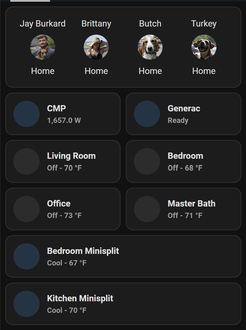
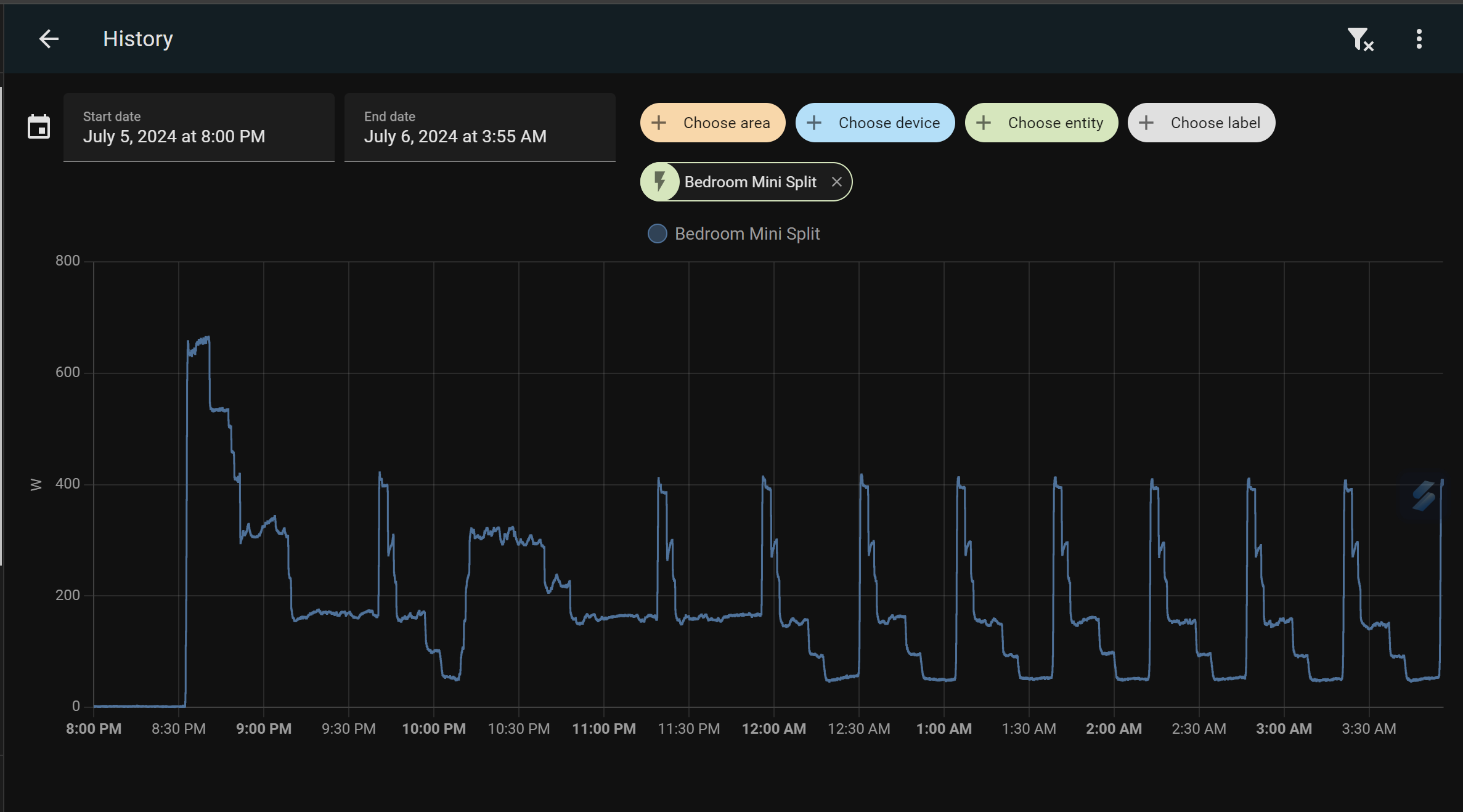
To monitor my energy usage, I swapped one of the CTs from my all-local emporia Vue ESPHome setup from a low usage circuit to one leg of the minisplit. I reconfigured the ESPHome yaml to account for it being just 1 of the 2 power legs (2x multiplier). I was extremely satisfied with what I saw - the split cycled up to about 700w on startup and then idled down to under 400 for the entire rest of the evening. Most of the time, it was running below 200W. Ambient temperature wasn't crazy high (high 70s, cooling bedroom to 69F). I'll be interested to see what usage looks like in a more extreme scenarios later this summer/into the winter.